


2026-03-31
How to choose a magnetic grid ruler reading head? Product selection guide for machine tools, woodworking, and lithium battery production lines
Magnetic grid ruler reading headThe value lies not in the empty phrase 'replacing grating rulers', but in its ability to provide more stable position feedback under conditions such as oil pollution, dust, vibration, and long-distance operation. The most prone to errors when selecting is not the accuracy itself, but the matching of magnetic pole spacing, output level and controller interface, cable environment adaptation, and installation gap control. By sorting out these questions, the selection of models in the future will be much clearer.
In CNC machine tools, woodworking machinery, stone cutting, lithium battery equipment, and hydraulic systems, once displacement feedback becomes unstable, the consequences are often not as simple as "inaccurate data", but rather product deviations, repeated alarms, maintenance shutdowns, and even slowing down the entire equipment cycle. Many engineers come into contact for the first timeMagnetic grid ruler reading headThe most common question asked is: How should I choose this thing?
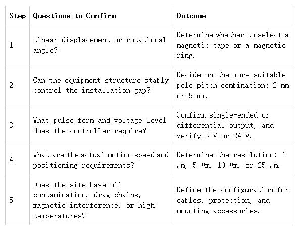
The conclusion is that the selection of the magnetic grid ruler reading head is not based on the brand or the advertised "high precision", but on determining whether the application is linear or rotary, whether the magnetic pole distance is 2mm or 5mm, whether the controller needs single ended or differential, whether the power supply is 5V or 24V, and whether the installation gap can be stably controlled on site. If these five things are not thought out clearly in the early stage, even if you buy the right model later, you may still install an unstable system.
1、 Don't rush to choose the model yet, judge firstMagnetic grid ruler reading headIs it suitable for your working conditions
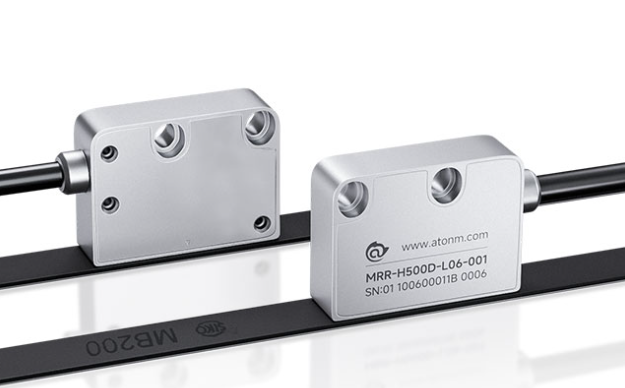
The magnetic grid ruler reading head is essentially a non-contact displacement measurement system. It does not work alone and must be used in conjunction with magnetic strips or rings. Its advantages are very clear: anti pollution, anti vibration, can be used for long distances, and relatively low maintenance pressure. So it's not necessarily "better" in all scenarios, but more suitable in harsh working conditions.
Q: Why are many machine tools and automation equipment considering magnetic grid scale reading heads?
Answer: It's not because it's "more advanced", but because many on-site problems are not algorithm problems, but environmental problems. Oil stains, dust, iron filings, and vibrations will first drag down the optical scheme, and no matter how well the system compensates, it cannot save a continuously distorted feedback signal.
2、 The first step in selecting the magnetic grid ruler reading head is to separate the straight line scene from the rotating scene
This is the earliest mistake that many projects make. Although the reading head is the core, it must be matched with the backend carrier. doLinear displacement measurementTo be equipped with a magnetic stripe; To measure the rotation angle, a magnetic ring is required. It may seem like the attachments are different, but in reality, the installation structure, origin requirements, space limitations, and debugging methods are all different.
1. Linear displacement measurement scenario
If your device is for worktable movement, slide table positioning, tool travel feedback, or module displacement control, all of these belong to linear scenarios. The corresponding usually ismagnetic stripeSystems are commonly used in machine tools, woodworking machinery, stone equipment, lithium battery guides, injection molding, and hydraulic stroke control.
2. Scene for measuring rotation angle
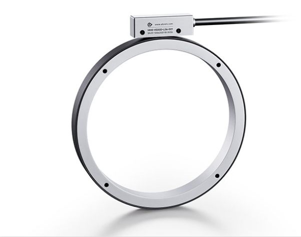
If your device is a rotating worktable, motor spindle, turntable positioning, and large aperture angle measurement, then the magnetic ring solution is more suitable. The key to a magnetic ring is not only size matching, but also whether it needs to have a Z-direction origin, upper speed limit, and whether it needs a stainless steel protective ring to resist the risk of high-speed flying.
flowchart TD
A [Start Selection] -->B {What is the measurement object}
B --> |Linear displacement | C [magnetic stripe system]
B --> |Rotation angle | D [magnetic ring system]
C --> E [Confirm magnetic pole distance of 2mm or 5mm]
D --> F [Confirm outer/inner diameter and whether Z origin is required]
E --> G [Select Read Head Output Resolution and Signal Type]
F --> G
G --> H [Check the interface between the power supply voltage and the controller]
H --> I [Review installation gap and cable environment]
3、 How to choose the magnetic pole distance? This is the most easily overlooked hard condition in the selection of magnetic grid scale reading heads
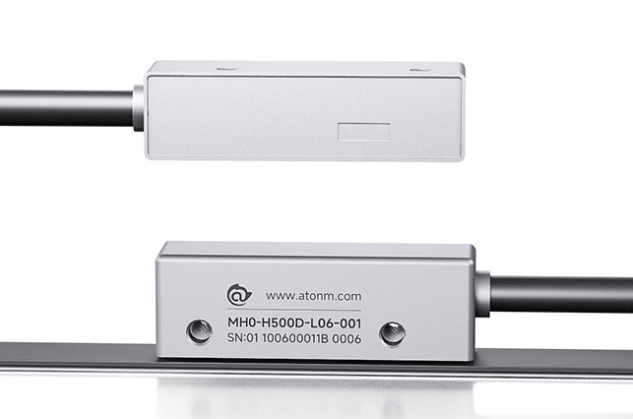
Atorm's current main magnetic grid rulerreading headIt can be understood as unfolding around two types of magnetic pole spacing configurations: H200 corresponds to a 2mm magnetic pole spacing, and H500 corresponds to a 5mm magnetic pole spacing. This is not a naming difference, but an underlying matching relationship. If the magnetic pole distance is selected incorrectly, all subsequent parameters will lose their meaning.
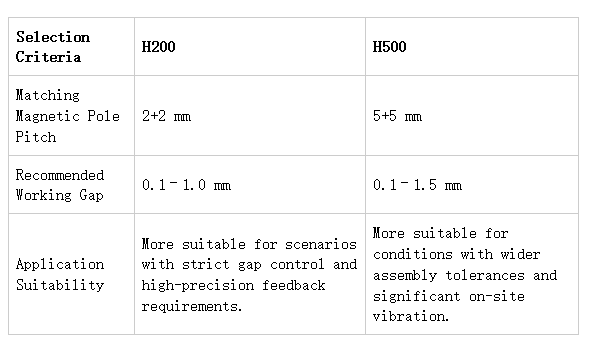
Applicable judgment is more suitable for scenarios with stricter gap control and higher requirements for fine feedback. It is more suitable for working conditions with wider assembly margins and more obvious on-site vibrations
Simply put, the 2mm pole spacing scheme usually requires stricter installation control; The 5mm magnetic pole spacing scheme is more flexible in terms of mechanical assembly tolerance. If the rigidity of the on-site equipment structure is average, the installation space is limited, and the level of assembly personnel is uneven, then we cannot only focus on the "theoretical accuracy", but must also take into account the consistency of later installation.
Question: Is it necessarily better if the magnetic pole spacing is smaller?
Answer: Not necessarily. A smaller magnetic pole distance usually means that the system has higher requirements for installation accuracy. If the vibration of the equipment body is large, the rigidity of the support is insufficient, and the clearance is difficult to control, the theoretical advantages may be offset by on-site assembly errors.
4、 The higher the resolution, the better. First consider the control requirements, and then look at the speed boundary
When many procurement or new project engineers choose displacement sensors, their first reaction is "the higher the accuracy, the safer it is". This logic does not always hold true in industrial settings. The magnetic grating scale reading head supports different resolutions such as 1 μ m, 5 μ m, 10 μ m, and 25 μ m. The real question to ask is whether your control system really needs such fine pulse resolution, and whether the device speed will push the output frequency to the boundary.
Given the product parameters, the maximum detection speed of the system can reach 8m/s, and the output frequency boundary is not higher than 2000kHz. The finer the resolution is set, the higher the number of pulses per unit distance, and the higher the requirements for the controller's high-speed counting ability and signal quality. If the controller cannot keep up, even the highest resolution is only a paper parameter.
Practical suggestion:
The equipment is mainly based on positioning control and repeatability accuracy, and the controller has sufficient high-speed counting capability, which can prioritize evaluating 1 μ m or 5 μ m.
Equipment emphasizes stable operation, anti-interference, and convenient wiring, with 10 μ m or 25 μ m often being more reliable.
High speed long-distance equipment must simultaneously check the operating speed, pulse frequency, and input upper limit of PLC or motion control card.
5、 The output signal and supply voltage are the easiest places to damage the project
This point must be mentioned separately. The information is already very clear:reading headThe output pulse signal level strictly follows the supply voltage. Power supply 24V, single ended output is 24V; power supply 5V, differential output is 5V. Many on-site faults are not due to inaccurate sensors, but rather interface mismatch.
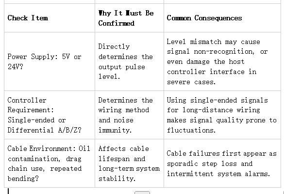
If your current PLC or motion control card only accepts 5V encoder signals, you cannot directly apply 24V to the reading head just because of the convenience of on-site power supply. This problem may sound basic, but it is precisely the root cause of a large number of project rework. The truly safe approach is to check the controller interface specification table and sensor interface specification table together during the initial selection stage, and not wait until the wiring to discover the problem.
6、 Poor gap control during installation, even the best magnetic grid ruler reading head cannot run steadily
The gap conditions provided in the information are already very clear. The working face of H200 should be controlled at a height of 0.1-1.0mm from the magnetic stripe, while H500 should be controlled at a height of 0.1-1.5mm. This is not a "recommended value", but a basic prerequisite for the stable operation of the system. During on-site debugging, many signals fluctuate intermittently, and upon inspection, it is found that the issue is not with the chip or software, but rather with the installation bracket jumping or the reference surface being uneven.
If there is significant thermal deformation, mechanical shaking, or workpiece impact during equipment operation, then when selecting, priority should be given to solutions with wider assembly margins, and the rigidity of the support should be evaluated simultaneously. Simply pursuing finer resolution without leaving room for installation will definitely incur costs on site.
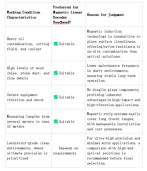
7、 How to choose the magnetic grid ruler reading head in different scenarios
1. CNC machine tools, grinders, lathes
This type of device focuses on the stability of position feedback and processing consistency. If there is cutting fluid, oil stains, and strong vibrations on site, the magnetic grid ruler reading head is more practical than traditional optical feedback. It is recommended to prioritize checking the controller interface, installation benchmark accuracy, and resolution requirements, rather than just looking at theoretical parameters.
2. Woodworking machinery and stone cutting equipment
The key to this type of scenario is not "high-precision", but rather the high amount of dust, difficulty in cleaning, and equipment that cannot be moved or stopped. The advantages of the magnetic grid system here are very direct, with a focus on selecting combinations that have strong anti pollution capabilities, convenient wiring, and sufficient installation margin.
3. Lithium battery and photovoltaic automation production lines
This type of production line often encounters longer guide rails and high-speed displacement control. When selecting, priority should be given to long-distance magnetic stripe schemes, output frequency boundaries, and counting capabilities at high speeds. If necessary, differential output should be given priority to reduce the risk of long-distance transmission interference.
4. Robot and Rotation Axis Control
If angle measurement is done in conjunction with magnetic rings, the focus shifts from "length" to "size, origin, and speed". For devices that require origin reset, it is necessary to determine in advance whether to customize the Z-direction origin; For high-speed rotation or high-temperature conditions, the stainless steel protective ring scheme needs to be evaluated.
8、 Understanding the selection sequence of magnetic grid ruler reading heads with a table
9、 Selection conclusion:MagnescaleReading heads are not a universal solution, but they are usually more practical in harsh working conditions
If your device has a clean working environment, high structural rigidity, good maintenance conditions, and the project pursues extreme accuracy, then you can continue to make detailed comparisons with high-level optical solutions. But if your device operates year-round in environments with oil stains, dust, iron filings, vibrations, or long-distance scenarios, thenMagnescaleReading heads are often not a compromise, but rather a choice that is closer to the reality on site.
The truly effective selection sequence is to first consider the working conditions, then the mechanical structure, then the interface, and finally the model. Reversing the order is the easiest way to buy a system that looks beautiful in parameters but is unstable when implemented.
If you are already working on machine tool, woodworking, lithium battery or rotary shaft projects, the most time-saving way is not to compare prices first, but to organize the controller interface, stroke length, running speed, installation space and on-site photos first. The Atorm technical team can provide more on-site recommendations for magnetic grid scale reading heads, magnetic strips, or magnetic ring combinations based on this, and assist in determining whether the 2mm/5mm magnetic pole spacing, resolution, and signal output scheme match.
You May Be Interested
-
Atonm MDSC-9000T Dual-Channel, Single-Sensor Metal Double-Sheet Detector
2025-12-05
-
Non-Contact “One-to-Four” Double-Sheet Detector 1600S: A New Cost-Reduction and Efficiency Solution for Stamping Lines
2025-11-20
-
Mold damage, production delays? Atonm MDSC-8200T metal double-sheet detector protects automotive stamping lines
2025-10-30
-
Provincial Auto Industry Research Tour | Atonm Engages with the Automotive Supply Chain, Empowering Smart Manufacturing through Sensors
2025-10-11