



2026-06-29
Does the laser displacement sensor have no numerical value for measuring stainless steel? First, clarify which type of stainless steel it is
Key points
Stainless steel has two surface states: mirror and matte. The core reason for the lack of numerical values caused by mirror stainless steel is Specular Reflection, where the laser bounces back and cannot enter the receiving lens. Triangular measurement relies on diffuse reflection signals. When the incident angle is equal to the reflection angle, the offset installed receiver cannot receive light, and the signal loss rate is close to 100%. There are three solutions: inclined installation (the simplest), coaxial optical path design (the cure solution), and surface treatment (emergency measures)
Install the laser displacement sensor and align it with the stainless steel workpiece. The display screen is blank - there is no value.
This is one of the most common "paranormal events" on the debugging site. The sensor is not broken, the wiring is fine, and the range is sufficient, but it just cannot read the data.
Where is the problem? On that piece of stainless steel. But not all stainless steels cannot be tested, the key is the surface condition.
Mirror reflection: the "pinball table" of laser
Laser displacement sensorThe core principle of the triangulation method is that the transmitter emits a laser beam onto the surface being measured, the receiving lens receives the reflected light from another angle, and the distance is calculated through triangular geometric relationships.
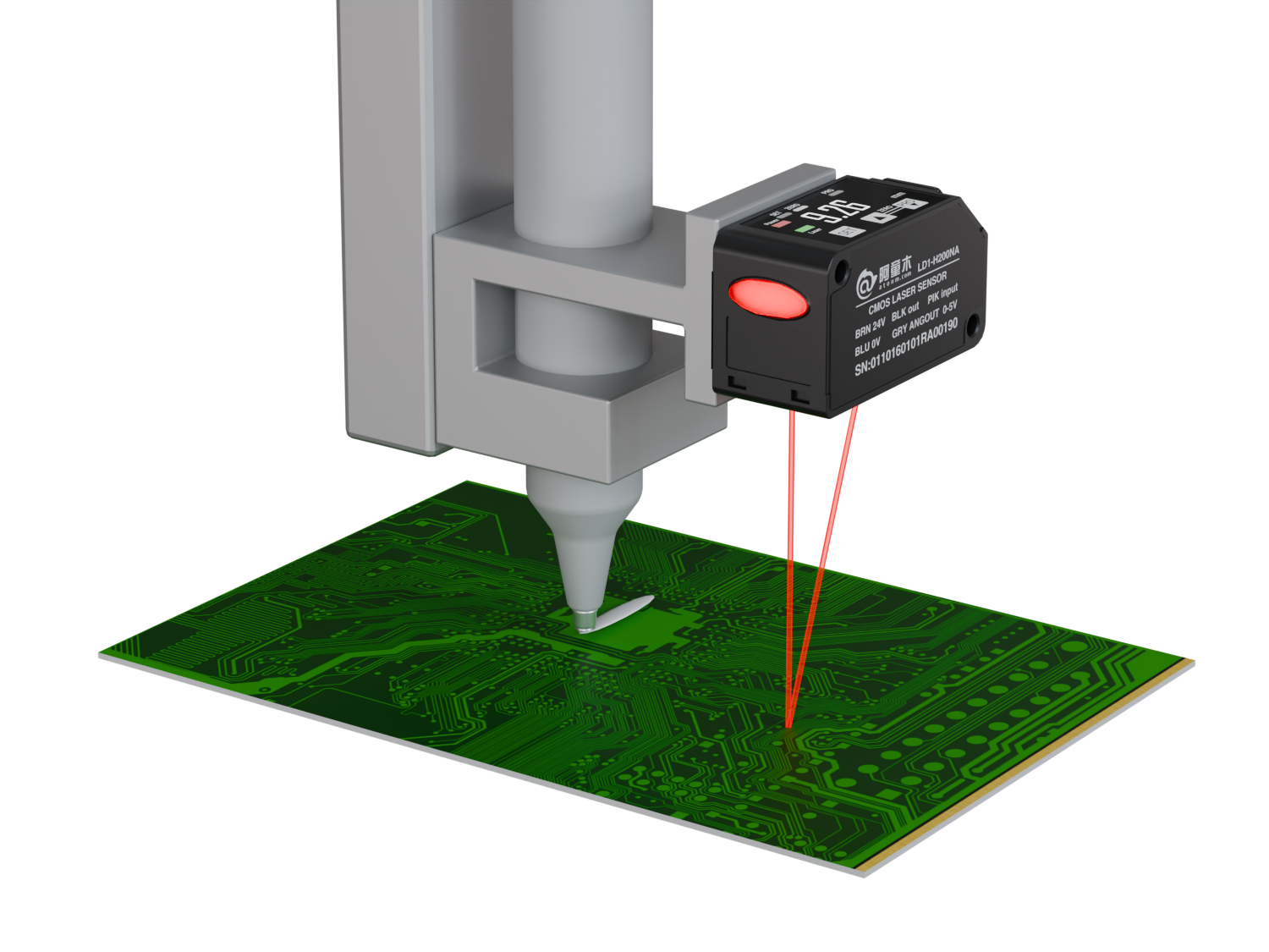
The premise for this logic to hold is that the tested surface can scatter the laser in all directions, and the receiver can always "catch" a part of it.
But mirror stainless steel is not like that.
Its surface roughness is extremely low (polished surface with Ra<0.4 μ m), and when laser hits it, it is not scattering, but specular reflection - the incident angle is equal to the reflection angle, and the laser beam bounces out in the original direction like hitting a mirror.
The problem is that the receiving lens and the transmitter are not on the same optical axis (a basic requirement of trigonometry), all the light reflected by the mirror bounces elsewhere, and the receiver cannot receive a single drop of light. The received light intensity approaches zero, and the sensor naturally cannot calculate the distance.
This is not a sensor malfunction, it is a physical law - you cannot use a system that relies on diffuse reflection to measure a surface that only does specular reflection.
Both are "stainless steel", some can be measured while others cannot
Stainless steel is not a uniform material category. Classified by surface condition:
| Surface type | roughness | Reflection characteristics | Can it be measured normally |
| Mirror polishing (BA/8K surface) | Ra<0.1μm | Over 95% specular reflection | ❌ Almost impossible to measure |
| Brushed/frosted | Ra 0.4-1.6μm | Mainly diffuse reflection+a small amount of specular reflection | ✅ Can be measured normally |
| Sandblasting/Acid Cleaning | Ra 1.6-6.3μm | Strong diffuse reflection | ✅ Measurement stability |
| Cold rolled 2B surface | Ra 0.1-0.4μm | Mixed reflection | ⚠️ Partial angle measurable |
Did you see the pattern? The smoother the surface, the closer it is to a mirror, and the more difficult it is to measure. The brushed surface and sandblasted surface have sufficient micro roughness to scatter the laser and ensure the normal operation of the sensor.
So the first reaction should not be 'the sensor is broken', but rather to see what surface condition the stainless steel you are measuring is.
Three solutions
Confirmed that it is a mirror reflection problem, there are three ways to deal with it, arranged in order of implementation difficulty:
Option 1: Tilt installation (simplest, zero cost)
Tilt the sensor at an angle (usually 5 ° -15 °) relative to the stainless steel surface to allow the specular reflection of light to deviate from the "blind spot" of the receiver, while utilizing the diffuse reflection component generated by the micro roughness of the surface.
This method utilizes the geometric properties of trigonometry - when tilted, the angular relationship between the receiving lens and the diffuse reflected light changes, allowing it to 'catch' a portion of the scattered light. When the deviation of the incident angle exceeds * * ± 15 °~30 ° * *, it may cause signal loss, so the tilt angle needs to be controlled within a reasonable range, not the larger the better.
Advantages: No need to move the hardware, just adjust the installation bracket.
Disadvantages: The accuracy may slightly decrease, and the effect on super mirror surfaces with Ra<0.1 μ m is limited.
Option 2: Coaxial Optical Path Design (Radical Solution)
The sensor, transmitter, and receiver of Coaxial Optical Design share the same optical axis and are split by a half mirror. The light reflected by the mirror returns along the original path and can enter the receiver through the spectroscope.
This is a fundamental solution to the problem of specular reflection from an optical structure perspective. Strong reflective/mirror materials (such as stainless steel mirrors and float glass) require specialized mirror reflective laser displacement sensors, with coaxial optical paths being the core design difference.
Advantages: Both mirror and highly reflective metals can be measured stably without affecting accuracy.
Disadvantage: The price of coaxial optical path sensors is usually 30% -50% higher than standard trigonometric models.
Option 3: Surface Treatment (Emergency Measures)
Stick a piece of matte tape and spray a layer of matte marking paint at the measurement point to turn specular reflection into diffuse reflection.
Advantages: Immediate results.
Disadvantages: Not suitable for online continuous detection, marks may wear and fall off, and additional measurement errors (tape thickness) are introduced. Only suitable for laboratory or temporary testing.
There is another easily overlooked variable: ambient light
Stainless steel workshops usually have strong lighting, coupled with welding arc light and direct sunlight from fluorescent lamps, the ambient light may exceed the intensity of laser reflection signals. According to the on-site debugging experience of Atorm sensors, in direct sunlight or strong light environments, ambient light may drown out weak laser reflection signals.
If the signal is still unstable after adjusting the angle, try blocking the light first - installing a light shield or increasing the threshold filter in the sensor software.
Summary of Investigation Sequence
If there is no numerical value for stainless steel, check in this order:
1. First, look at the surface: is it mirror or matte? Mirror → Most likely a reflection issue
2. Adjust the angle again: tilt 5 ° -15 ° and see if there is a signal coming out
3. Check ambient light: block strong light and eliminate interference
4. Check the wiring and power supply: eliminate hardware faults (this probability is the lowest)
5. None of the above works: Consider replacing the coaxial optical path sensor
FAQ
Q1:Laser displacement sensorCan all stainless steel be tested?
No. Matte surfaces such as brushed surfaces, sandblasted surfaces, and acid washed surfaces can be measured normally; Mirror polished surfaces (Ra<0.1 μ m) may result in the receiver not receiving a signal due to mirror reflection, leading to a situation of no value. The key is to look at the surface roughness, not the material.
Q2: How much will the accuracy decrease after inclined installation?
The small angle tilt (5 ° -15 °) has little impact on accuracy and is usually within the allowable error range. Excessive tilt angle (over 30 °) can cause significant signal attenuation or even loss. Suggest starting from small to large keys and finding the smallest angle that can produce a signal.
Q3: What is the difference between coaxial optical path sensors and ordinary triangulation sensors?
The core difference lies in the optical path structure. The transmitter and receiver of the triangulation method are separated and rely on diffuse reflection; The transmitter and receiver of the coaxial optical path share the optical axis, and the light energy reflected by the mirror returns to the original path for reception. So coaxial type can measure mirror/high reflective materials, ordinary triangulation method cannot.
You May Be Interested
-
Atorm has been awarded ISO three system certification, safeguarding quality and sustainable development with international standards
2026-10-12
-
Atonm MDSC-9000T Dual-Channel, Single-Sensor Metal Double-Sheet Detector
2025-12-05
-
Non-Contact “One-to-Four” Double-Sheet Detector 1600S: A New Cost-Reduction and Efficiency Solution for Stamping Lines
2025-11-20
-
Provincial Auto Industry Research Tour | Atonm Engages with the Automotive Supply Chain, Empowering Smart Manufacturing through Sensors
2025-10-11