


2023-02-15
Double-Sheet Detection Sensor | MDSC-900E Metal Double-Sheet Detector User Guide
The MDSC-900E series Metal Double-Sheet Detector, independently developed and manufactured by Atonm (Guangzhou) Intelligent Technology Co., Ltd., is specially designed for automatic feeding systems in the stamping industry. It detects thickness differences in various metal sheets (such as aluminum, iron, copper, stainless steel) to effectively prevent double or multiple sheets from entering subsequent processing steps, which could cause defective products or damage molds. The product includes a detection host and sensor.

This guide introduces the specifications, features, and usage of the MDSC-900E Metal Double-Sheet Detector. Please read carefully before using the 900E to better understand product characteristics and ensure safe use.
1. Safety Precautions
◆ Ensure the operating environment meets the limits specified in the hardware specifications (refer to Performance Parameters for details);
◆ Do not install in areas with strong magnetic fields, direct sunlight, high temperatures, or severe mechanical vibration. Do not use in environments with flammable gases, vapors, or dust to avoid explosion risk;
◆ Do not use in environments with drastic temperature changes or very high humidity, which may cause internal condensation and damage the device;
◆ Ensure all cable connections to the product are secure. Loose connections may cause incorrect input or output signals;
◆ Avoid using tools to touch the display panel during operation; damage from excessive force is the user's responsibility;
◆ To avoid electric shock, disconnect power before connecting the product to power;
◆ The input power is DC24V ±20%; periodically check that the DC power is stable;
◆ NPN and PNP interfaces are for DC systems below 48V only;
◆ Keep sensor wiring separate from power wiring, especially near inverters or strong interference sources.
2. Performance Parameters
1. Product name: MDSC-900E Metal Double-Sheet Detector
2. Host dimensions: 132mm * 116mm * 48mm
3. Cutout size: 121mm * 105mm
4. Sensor sizes (choose one)
Square sensor: 45mm * 30mm * 12mm with standard 5m cable
M18 round sensor: diameter 18mm * length 50mm with standard 5m cable
Small square sensor: 30mm * 18mm * 10mm with standard 5m cable
5. Input power: DC24V/500mA
6. Control outputs:
1. NPN single/double-sheet switch signal output, max drive 50mA/48V
2. PNP single/double-sheet switch signal output, max drive 50mA/48V
Note: Single and double-sheet output pulse width default is 50ms at factory
7. Adjustable range: 5 - 500ms
8. Detectable materials:
Steel, iron, copper, aluminum, galvanized sheet, stainless steel, etc.
9. Detectable thickness:
Iron, copper, stainless steel 0.1 - 2.5mm; aluminum 0.1 - 8mm
10. Response speed: 0-200 pcs/min
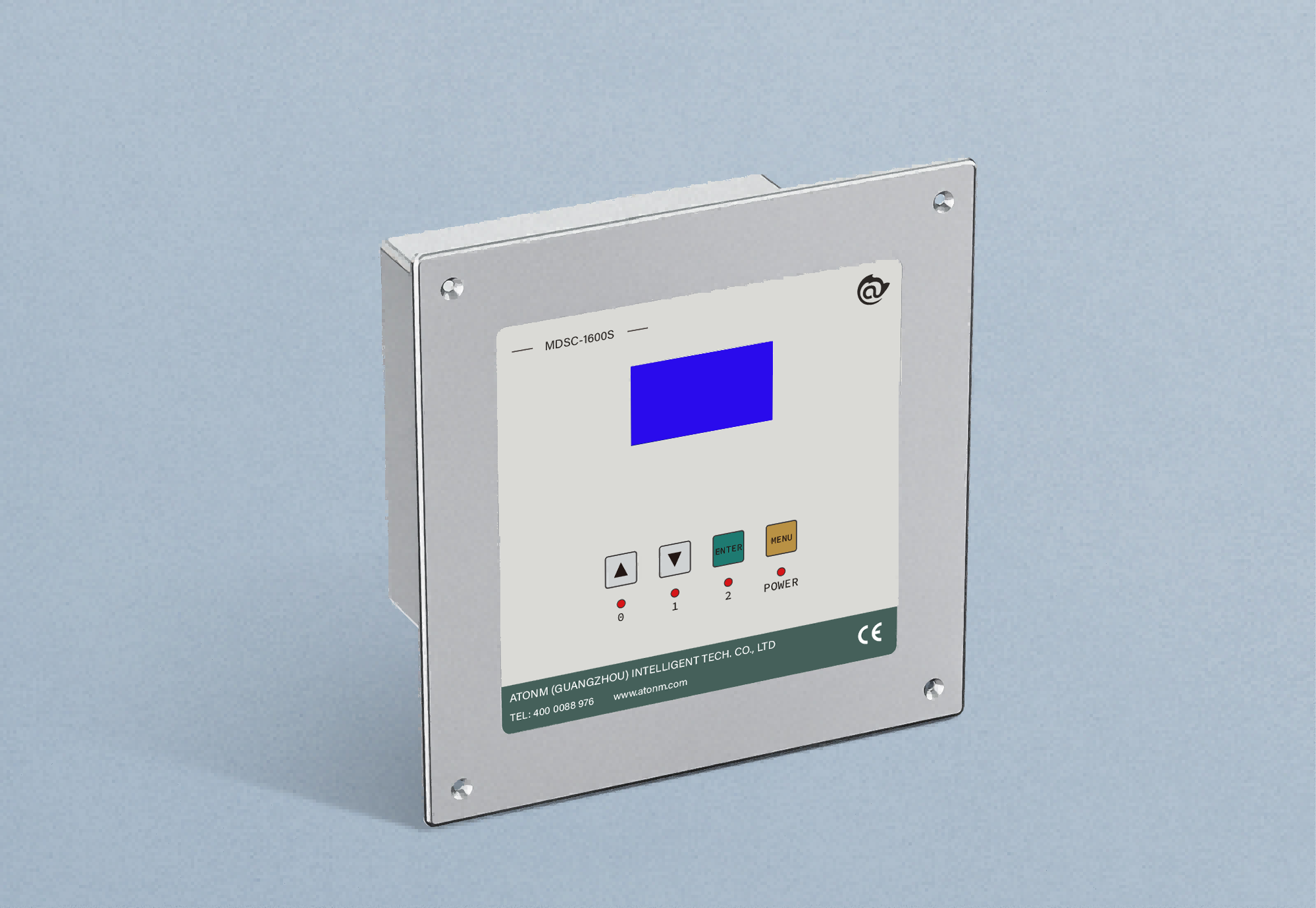
3. Front panel and function description
(a) LCD display


(b) Button operations
Button | Function description
|
Confirm
| 1. Long press 3 seconds to enter setting mode (including auto-adjust and learning modes). The LCD backlight will turn on and NPN/PNP outputs will be disabled. Short press to confirm the current operation; 2. In setting mode, short press Confirm to select single/double-sheet sensitivity; 3. In learning mode, short press Confirm to save current learning data. |
Back
| 1. Cancel previous operation; 2. In setting mode, long press 3 seconds to exit setting mode and return to working mode. |
Up/+ 1
| Short press increases the selected value; long press continuous increase. |
Down/- | Short press decreases the selected value by 1; long press continuous decrease. |
Auto adjust | Short press Auto Adjust to enter auto-adjust mode. |
Zero setting
| With no sheet, short press Zero Setting; the zero indicator will flash, then short press Confirm to save. |
Single-sheet setting
| 1. In auto-adjust mode: place a single test sheet and short press Single-sheet Setting. Three LEDs will flash. After a few seconds, only the Double-sheet LED will flash, indicating single-sheet auto-adjust is complete. 2. In dynamic learning mode: short press Single-sheet Setting; single-sheet LED will flash. Control the feeder to pass one test sheet, then press Confirm to save.
|
Double-sheet setting
| 1. In auto-adjust mode: place two stuck sheets for testing and short press Double-sheet Setting. Three LEDs will flash. After a few seconds all three LEDs will remain on, indicating double-sheet auto-adjust is complete. 2. In dynamic learning mode: short press Double-sheet Setting; double-sheet LED will flash. Control the feeder to pass two stuck sheets and press Confirm to save. |
Note: All buttons are only operational after entering setting mode by long pressing Confirm; otherwise they have no effect.
(c) LED indicators
LEDs indicate detection state in real time: zero sheet = blue on; single sheet = blue and green on; double sheet = blue, green, and red on. In learning mode, corresponding LEDs flash to show learning in progress.
(d) Modbus memory group switching
The device supports switching memory groups via Modbus over RS485 using Modbus-RTU. Write the target memory group number (0~99) to register 0000H (power-off retain) or A000H (no retain) to switch groups. Read and write are supported for both 0000H and A000H.
Example: 1. Write memory group 3 (03H) to register 0000H assuming device address 16 (10H)
Send (hex): 10 06 00 00 00 03 CA 8A
Response (hex): 10 06 00 00 00 03 CA 8A
2. Read register 0000H assuming device address 16 (10H)
Send (hex): 10 03 00 00 00 01 87 4B
Response (hex): 10 03 02 00 03 04 46
Frequent writes to 0000H may damage the chip; if the host repeatedly writes on power-up, use A000H group.
(e) IO input memory switching
The device has 2 IO inputs (X0, X1). When Modbus baud rate is set to 0, these inputs can switch memory groups 0~3. See the table below.

Memory group switching must be done via communication or terminal; it cannot be modified on the panel for the currently displayed group for learning or usage.
4. Installation and wiring
(a) Host installation
Cut a 121mm * 105mm rectangular hole in the panel, insert the detection host, then insert the fixing clips at the upper and lower openings of the host and tighten the screws.
(b) Sensor installation
Install the Metal Double-Sheet Detector sensor on a metal or plastic bracket as shown. Place the transmitter T at the top and the receiver R at the bottom; ensure the working face (with the black circular surface) faces the installation. Allowable installation distance is 30~50mm; recommended distance is 40mm. For thicker magnetic materials (>2mm) or small-area samples (diameter < 10cm), set distance to 30mm. For thinner non-magnetic materials (<0.5mm), set distance to 50mm.
When detecting feed, ensure the test metal passes through the effective sensing area (at least aligned approximately with the inner edge of the sensor; can be moved slightly inward). Recommended installation positions are shown. Note: the sensor sight area must be clear of other metal obstructions.

(c) Assembly wiring diagram

(d) Electrical control wiring diagram
(e) 
5. Host commissioning steps
Install the detection host and sensor as required and connect the electrical control wiring. Power on; if the LCD displays normally, the host is in working mode. If learning data for the sheet has been saved previously and the sheet and relative position remain unchanged, you can select the saved memory group via serial port or IO input. Otherwise, choose a memory group to save the current sheet learning data and follow the steps below.

① Long press Confirm for 3 seconds until the LCD lights and enter setting mode. Short press Auto Adjust; the single-sheet indicator will flash to enter auto-adjust mode.
② Control the feeder to deliver one sheet to the sensor center and stop. Place the sheet so its largest area is centered on the sensor. If feeder control is not available, manually place one sheet in the sensor gap consistent with feeder position. Short press Single-sheet Setting and wait until only the Double-sheet red LED flashes, then remove the single sheet to complete single-sheet adjustment.
③ Control the feeder to deliver two stuck sheets. If feeder control is not available, manually place two sheets together. Short press Double-sheet Setting and wait until all three LEDs remain on, then remove the double sheets to complete double-sheet adjustment.
④ Remove sheets to clear the sensor gap and short press Zero Setting; the zero indicator will flash. Short press Confirm to save and complete zero setting. Long press Back to exit auto-adjust mode and return to working mode. After learning, data is saved to the current memory group.
(2) Dynamic learning (optional)
If auto-adjust results are not ideal and excessive false positives or misses occur (especially when sheets move laterally during detection and static learning points are hard to capture), add dynamic learning after auto-adjust.

⑤ In setting mode (long press Confirm 3 seconds), short press Single-sheet Setting; the single-sheet green LED will flash. Control the feeder to pass one sheet dynamically, then short press Confirm to save and complete single-sheet dynamic learning.
⑥ Short press Double-sheet Setting; the double-sheet red LED will flash. Control the feeder to pass two stuck sheets dynamically, then short press Confirm to save and complete double-sheet dynamic learning.
⑦ After settings, long press Back for 3 seconds; LCD backlight turns off and device returns to working mode. Settings are complete and detection can begin. Recalibrate when changing sheet specifications or feed position significantly.
(3) Manual settings (optional)
If single or double detection is too insensitive or too sensitive, long press Confirm for 3 seconds to enter setting mode, then short press Confirm. The number next to Single will flash; adjust sensitivity with Up or Down and press Confirm to save, then proceed to double-sheet sensitivity and save. Press Back to cancel and restore previous sensitivity if needed. Non-professionals are not recommended to perform manual sensitivity tuning.
6. Engineering setting mode
Engineering mode allows adjustment of advanced parameters. Default factory settings suit most applications. Enter engineering mode only when defaults do not meet special requirements.
In working mode (LCD backlight off), press and hold Up and Down together for 5 seconds; backlight turns on and enter engineering mode.
Press Confirm to select a parameter (it will flash). Adjust with Up or Down and press Confirm to save and move to the next parameter. Engineering mode display example shown below:

1. Single judgment sample count, 2 digits, range 0~99. Each sample time is 5ms. For example, set to 2 means single judgment samples 2 times (total 10ms). All samples must exceed single/double thresholds to be judged as single/double. More samples increases noise immunity but slows response.
2. Minimum output hold time, 2 digits, range 0~99. Base 5ms. For example, set to 10 means min output time is 50ms.
3. Sensitivity adjustment mode, 1 digit, range 0~1. Set 0: single sensitivity is percentage between single learned value and zero learned value; double sensitivity is percentage between double learned value and single learned value. Set 1: single/double sensitivity is percentage within the entire signal range.
4. Output logic, 1 digit, range 0~1. Set 0 for normally open; set 1 for normally closed.
5. Modbus device address, 2 digits, range 1~99.
6. Signal bars, total 16 bars.
7. Modbus serial parity and stop bits, 1 digit, range 0~3 (see table).

8. Modbus baud rate, 1 digit, range 0~9. Set 0 to disable Modbus serial memory group switching (use IO switching). Other values correspond to baud rates in the table.
8. Warranty
1. The product warranty period is 18 months, based on machine barcode. Within warranty and under normal use as per the manual, Atonm provides free repairs.
2. During warranty, the following causes will incur repair charges:
● Damage caused by improper use or unauthorized disassembly, repair, or modification;
● Damage due to fire, flood, abnormal voltage, natural disasters, or secondary disasters;
● Hardware damage due to drops or transport after purchase;
● Damage caused by failure to follow the user manual;
● Failures caused by external equipment factors.
3. For service issues, contact Atonm promptly;
4. Purchasing the product implies agreement to the warranty terms. Atonm retains final interpretation rights.
Contact us
If you have any questions or suggestions during use, contact Atonm (Guangzhou) Intelligent Technology Co., Ltd.
Service hotline: 400 0088 976
Note: The company continuously improves and upgrades products; some parameters may change without notice.
You May Be Interested
-
Atonm MDSC-9000T Dual-Channel, Single-Sensor Metal Double-Sheet Detector
2025-12-05
-
Non-Contact “One-to-Four” Double-Sheet Detector 1600S: A New Cost-Reduction and Efficiency Solution for Stamping Lines
2025-11-20
-
Mold damage, production delays? Atonm MDSC-8200T metal double-sheet detector protects automotive stamping lines
2025-10-30
-
Provincial Auto Industry Research Tour | Atonm Engages with the Automotive Supply Chain, Empowering Smart Manufacturing through Sensors
2025-10-11