


2026-06-18
How to pair the magnetic grid reading head with the magnetic grid ruler?
Magnetic grid reading heads should not be mixed arbitrarily. When pairing, priority should be given to matching specifications, followed by mechanical installation calibration, and finally power on for alignment. The entire process is applicable to all incremental magnetic grid systems such as stamping, servo, injection molding, and machine tools.
1、 Step 1: Hard specification pairing (cannot be used directly without matching)
It must be completely consistent, otherwise the hop count, garbled code, no signal, and accuracy will be scrapped.
The pitch of the magnetic poles must be consistent: commonly 2mm/5mm, the pitch of the reading head and magnetic ruler does not match, and 100% cannot read normally
Power supply voltage matching: distinguish 5V/24V, directly burn the read head if mismatched
Signal protocol matching: differential A/B/Z, single ended signal, controller interface must correspond
Consistent resolution system: The interpolation parameters of the reading head and the subdivision parameters of the system must be matched and cannot be mixed with different brands or non-standard subdivisions
Do you need an interpolator: Some high-speed/high-precision reading heads must be equipped with dedicated interpolation modules and cannot be directly connected to PLCs
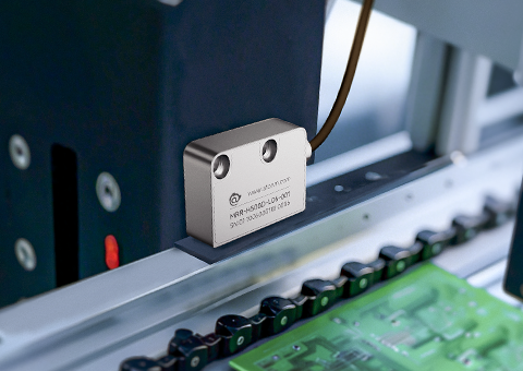
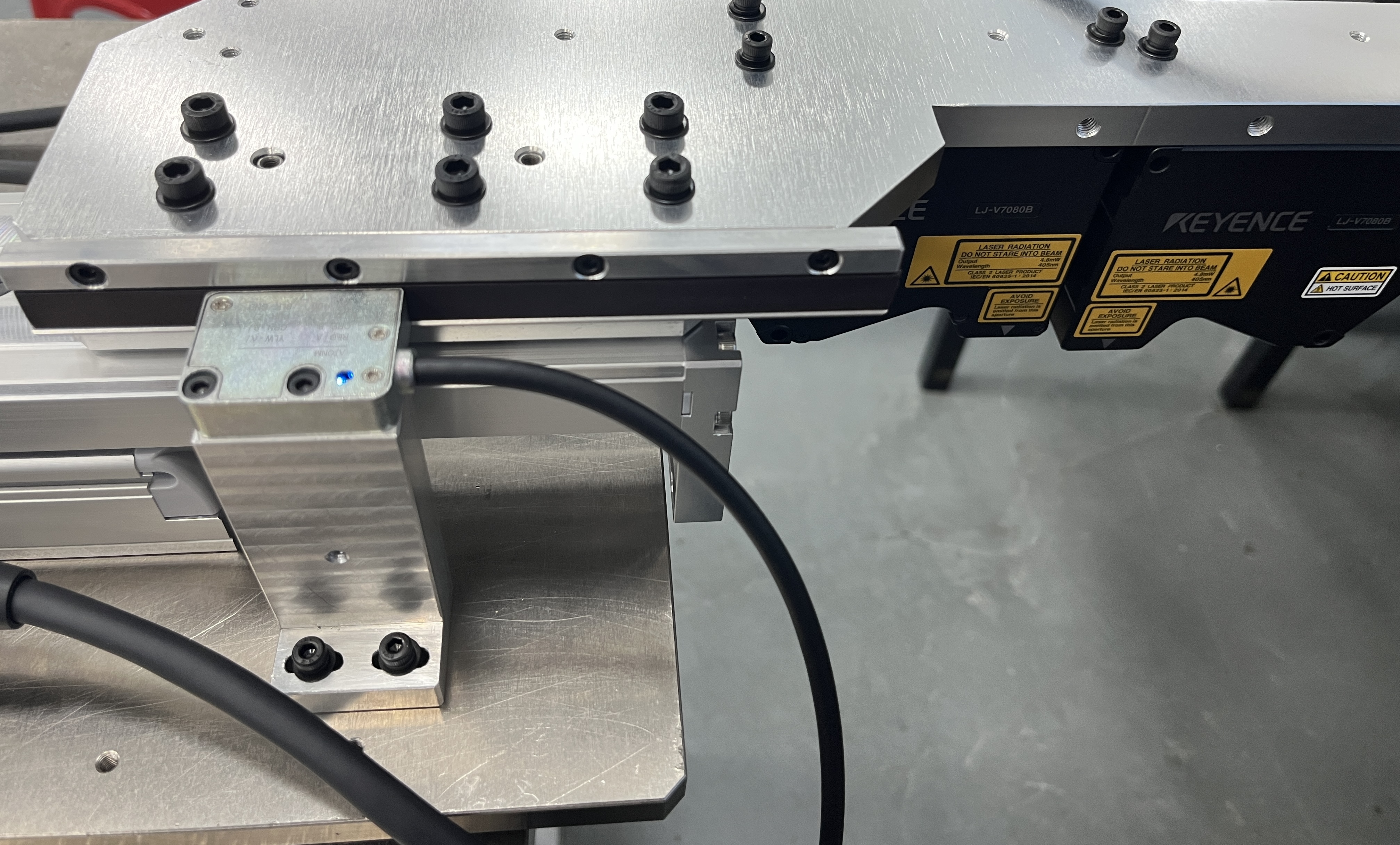
2、 Step 2: Mechanical installation pairing (determining stability, resistance to interference)
Magnetic grating belongs to near-field induction, and gap, parallelism, and no jitter are the pairing cores.
Standard sensing gap: Maintain 0.5-1.5mm throughout the entire journey (market standard), and do not rub against the ruler or fluctuate between large and small during the entire journey
Parallelism correction: The sensing surface of the reading head is completely parallel to the magnetic ruler surface, with no tilt left or right, front or back. Tilting can cause inconsistent signal strength and displacement at both ends
Installation of vibration and oil isolation: The reading head is firmly fixed without any looseness, and the surface of the magnetic ruler must be cleaned of oil and iron filings. The magnetic grid relies on magnetic field induction, and dirt will weaken the signal and cause jumping
Wiring specifications: The signal line should be kept away from the frequency converter and servo power line, and routed separately to prevent electromagnetic interference from causing reading drift
Expansion and contraction allowance of magnetic ruler: Reserve thermal expansion and contraction gaps at both ends of the magnetic ruler. Tight installation is prohibited as long-term operation may cause warping and delamination
3、 Step 3: Power on alignment+origin pairing (officially completed matching)
After mechanical adjustment, power on to complete the binding and alignment between the system and the magnetic grid.
1. Power on and confirm that the power light of the reading head is normally on without any alarm flashing
2. Manually drag the entire stroke and observe whether the reading is continuous, smooth, without jumping or lagging, and returns to zero
3. Start the system origin search, perform Z-phase origin alignment, and complete the binding of mechanical position and magnetic grid value
4. Run the journey back and forth multiple times to confirm that there are no missing numbers, no deviations, and no reverse drift
4、 Matching success criteria (acceptance criteria)
Continuous and stable readings throughout the entire journey, without any jumps, zero jumps, or numerical drift
Static state value does not jump (allowing ± 1 minimum unit shake is normal)
The origin Z-phase signal triggers accurately and the position is consistent every time
The readings are not disordered under oil pollution and vibration conditions
5、 Common reasons for pairing failure (quick troubleshooting)
Mismatch in pitch between old and new rulers and reading heads (most common)
Excessive gap/rubbing against ruler, parallelism deviation
Parallel interference between signal lines and power lines
Not connected to shielded wire, poor grounding
System subdivision parameters do not match the output of the read head
6、 Minimalist Summary (Quick Match Formula)
First, adjust the specifications (pitch/voltage/signal) → then adjust the gap parallelism → clean the dirt and avoid interference → calibrate the starting point of the electric running stroke → retest the stability
You May Be Interested
-
Atonm MDSC-9000T Dual-Channel, Single-Sensor Metal Double-Sheet Detector
2025-12-05
-
Non-Contact “One-to-Four” Double-Sheet Detector 1600S: A New Cost-Reduction and Efficiency Solution for Stamping Lines
2025-11-20
-
Mold damage, production delays? Atonm MDSC-8200T metal double-sheet detector protects automotive stamping lines
2025-10-30
-
Provincial Auto Industry Research Tour | Atonm Engages with the Automotive Supply Chain, Empowering Smart Manufacturing through Sensors
2025-10-11